
Many plastic parts cannot be molded with a simple open‑close tool. Features like side holes, snap‑fit barbs, and internal threads require moving components inside the mold. That is where slides and lifters come in. An injection mold with slides moves sideways to create external undercuts, while a lifter rises at an angle to release internal features. At Miracles Manufacturing, we specialize in designing and building complex molds with slides, lifters, and unscrewing mechanisms. Our engineers have decades of experience ensuring these components work reliably for millions of cycles. This page explains how we approach complex mold design, the key considerations, and how we help you avoid common pitfalls.
What Are Slides and Lifters?

Slides
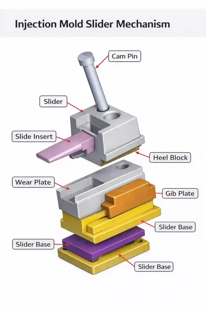
A slide is a movable block in the mold that retracts sideways after the plastic solidifies. It is used for:
- External side holes
- Undercuts on the outside of the part
- Features perpendicular to the mold opening direction
Slides are typically actuated by angled pins (horn pins) or hydraulic cylinders. When the mold opens, the angled pin forces the slide outward, clearing the undercut.
Lifters
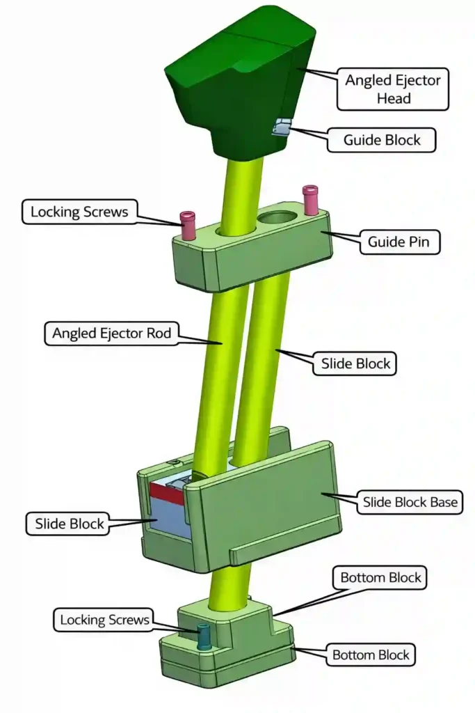
A lifter is a component that moves at an angle (usually 5° to 15°) to release an internal undercut, such as a snap‑fit hook or a barb. The lifter is attached to the ejector plate and rises as the part is ejected, lifting the feature out of the mold.
Unscrewing Mechanisms
For threaded parts, unscrewing molds use rotating cores driven by hydraulic motors, electric motors, or rack‑and‑pinion systems. The core unscrews as the mold opens, releasing the threaded feature.
Each of these mechanisms adds complexity to the mold – and cost – but they are essential for producing parts that cannot be molded otherwise.
For a complete overview of our mold engineering capabilities, visit our custom mold design services page .
Why Choose Miracles for Complex Molds
Decades of Experience
Our toolmakers have designed and built thousands of molds with slides, lifters, and unscrewing cores. We have seen every challenge and know how to solve them.
In‑House Design and Manufacturing
Everything is done under one roof – design, CNC machining, EDM, assembly, and testing. No outsourcing, no finger‑pointing. If there is a problem, we fix it fast.
Advanced Simulation
For complex molds, we use mold flow simulation to predict how the plastic will fill, where weld lines will form, and how slides and lifters will affect the process.
Quality Assurance
Every moving component is tested for smooth operation. We verify that slides retract fully, lifters do not bind, and unscrewing cores rotate freely.
Real‑scenario example: A client needed a mold with four slides and a hot runner system for an automotive part. Our team designed the slides with hardened wear plates and guided ejection to ensure long life. The mold has run over a million cycles with no issues.
Key Design Considerations for Slides
Slide Travel
The slide must move far enough to completely clear the undercut. A safety margin of 2–3 mm is typical. We calculate the required travel based on the undercut depth and part geometry.
Angle Pin Design
The angle pin (horn pin) drives the slide. The pin angle should be less than the slide travel angle to avoid binding. Common angles: 10° to 25°. Steeper angles move the slide faster but increase wear.
Wear Protection
Slides slide against steel surfaces. We use hardened wear plates (bronze or hardened steel) and lubrication grooves to extend life. For high‑volume production, we recommend DLC or TiN coatings.
Cooling
Slides often have limited cooling. We design cooling channels into the slide body or use high‑thermal‑conductivity materials like beryllium copper to improve heat transfer.
Return Mechanism
Slides must return to the molding position before the mold closes. Springs are common, but for large slides we use hydraulic cylinders for positive return.
Key Design Considerations for Lifters
Lifter Angle
Lifter angles are typically 5° to 15°. Steeper angles increase stress and may cause bending. We calculate the required angle based on the undercut depth and ejection stroke.
Lifter Head Design
The head of the lifter forms the undercut. It must have enough draft (0.5–1°) to release easily. Sharp corners at the base of the undercut are stress risers – we add radii to prevent cracking.
Lifter Body Strength
The lifter body must resist bending. We size it based on the projected area of the undercut and the ejection force. For long lifters, we may use guided ejection to prevent twisting.
Guiding
Lifters need precise guiding. We use bushings or guide pins to ensure smooth, straight motion. Without proper guiding, lifters can bind or break.
Cooling
Like slides, lifters are hard to cool. We use small cooling channels or high‑conductivity materials when necessary.
For parts requiring both slides and lifters, we integrate them seamlessly. Explore our advanced mold engineering solutions .
Unscrewing Mechanisms for Threaded Parts
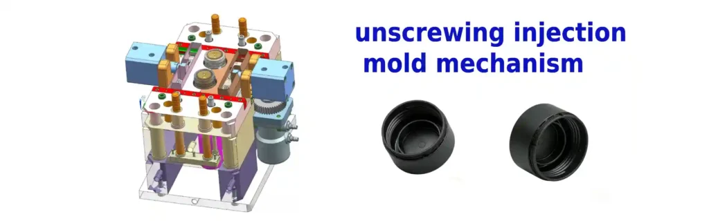
For parts with internal or external threads, unscrewing molds are the answer. Options include:
- Hydraulic unscrewing – Hydraulic motor drives the core, controlled by the molding machine.
- Rack‑and‑pinion – Mechanical system driven by mold opening.
- Electric unscrewing – Servo motor for precise control.
We help you choose the right system based on part geometry, volume, and cycle time requirements.
Common Design Mistakes and How to Avoid Them
| Mistake | Consequence | Solution |
|---|---|---|
| Insufficient slide travel | Part hangs up, mold damage | Calculate travel + 2–3 mm margin |
| Lifter angle too steep | Lifter bends or breaks | Keep under 15°, use stronger steel |
| No wear plates on slide | Slide wears quickly, flash | Add hardened wear plates |
| Sharp corners on lifter head | Stress cracks, part breaks | Add radii |
| Poor cooling | Long cycles, warpage | Add cooling channels or conductive materials |
| Slide return spring weak | Slide not reset, crash | Use stronger springs or hydraulic return |
| Unscrewing timing wrong | Threads damaged | Use limit switches or servo control |
Real‑scenario risk: A client had a mold with a 20° lifter. After 10,000 cycles, the lifter bent and the mold had to be rebuilt. We redesigned it with a 12° angle and a stronger steel – no further issues.
Design Checklist for Complex Molds
Slides
- Travel > undercut depth + 2 mm
- Angle pin angle ≤ 20°, less than slide travel angle
- Wear plates installed
- Cooling considered
- Positive return mechanism
Lifters
- Lifter angle 5–15°
- Lifter head tapered with radii
- Body thickness adequate (≥ 6 mm)
- Guiding provided
- Stress analysis performed for long lifters
Unscrewing
- Drive system selected (hydraulic, rack, electric)
- Timing verified
- Cooling for cores
Materials for Slides and Lifters
| Component | Recommended Material | Hardness |
|---|---|---|
| Slide body | H13, D2, or P20 (low volume) | 48–52 HRC |
| Wear plates | Bronze or hardened tool steel | – |
| Angle pins | H13 or D2 | 50–54 HRC |
| Lifter body | H13, S7, or M2 | 50–54 HRC |
| Lifter head | Same as body | – |
| Unscrewing cores | H13 with nitriding | 52–56 HRC |
For glass‑filled materials, we use coatings like TiN or DLC to reduce wear.
Frequently Asked Questions
Q1: How much does a slide or lifter add to mold cost?
A: Each slide can add $1,000–$5,000 to the mold cost, depending on size and complexity. Lifters add $1,000–$3,000. Unscrewing mechanisms add more.
Q2: Can I avoid slides by redesigning the part?
A: Sometimes yes. Rotating the part or splitting it into two pieces may eliminate undercuts. We can review your design and suggest alternatives.
Q3: What is the maximum angle for a lifter?
A: Typically 15°. Above that, stress increases significantly. For deeper undercuts, consider a two‑stage lifter or a hydraulic core.
Q4: Do slides and lifters need maintenance?
A: Yes. Wear plates, pins, and springs should be inspected regularly. Proper lubrication extends life.
Q5: Can slides be used on both sides of the mold?
A: Yes, slides can be on the cavity side, core side, or both. They can also be angled in multiple directions.
Q6: What is the best steel for glass‑filled materials?
A: H13 or D2 hardened to 52–56 HRC, plus coatings.
For more detailed design guidelines, refer to our comprehensive mold design guide .