
Many plastic parts have features that cannot be molded with a simple open‑close mold. Holes on side walls, snap‑fit barbs, internal threads – these all need moving components inside the mold. That is where slides and lifters come in. A slide moves sideways to create an undercut, while a lifter moves at an angle to release an internal feature. Designing these components correctly is critical for mold reliability and part quality. In this guide, we explain how slide injection molding works, when to use lifters, and the key design rules you must follow. Whether you are designing a new mold or troubleshooting an existing one, this article will help you avoid costly mistakes.
What Are Slides and Lifters?
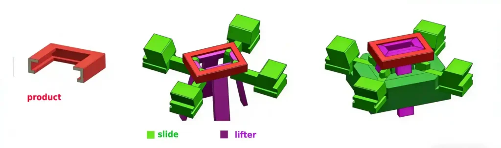
Slides
A slide is a movable block in the mold that retracts sideways after the part is molded. It is used for external undercuts, side holes, or features that are perpendicular to the mold opening direction. The slide is usually actuated by an angled pin (horn pin) that pushes it outward as the mold opens.
Lifters
A lifter is a component that moves at an angle (typically 5–15°) to release an internal undercut, such as a snap‑fit hook or a barb. The lifter rises as the mold opens, lifting the feature out of the part. Lifters are often part of the core and have a thin steel section that forms the undercut.
Unscrewing Mechanisms
For threaded parts, unscrewing molds use rotating cores. These are more complex and require hydraulic or electric motors to turn the core while the mold opens.
When to Use Slides vs. Lifters
| Feature Type | Recommended Mechanism |
|---|---|
| External side hole | Slide |
| External undercut (e.g., snap‑fit on outside) | Slide |
| Internal undercut (e.g., hook inside a box) | Lifter |
| Internal thread | Unscrewing mechanism |
| External thread | Slide or split cavity |
A common pitfall: Trying to use a lifter for an external undercut can lead to interference and mold damage. Always match the mechanism to the feature location.
Key Design Parameters for Slides
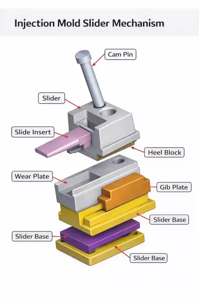
Slide Travel
The slide must move far enough to completely clear the undercut. A rule of thumb: travel = undercut depth + 2–3 mm safety margin.
Angle Pin Angle
The angle of the horn pin determines how fast the slide retracts. Common angles: 10° to 25°. Steeper angles move faster but increase wear. The pin angle should be less than the slide travel angle to avoid binding.
Slide Return
Springs or hydraulic cylinders return the slide to the molding position before the mold closes. Ensure enough force to overcome any resistance.
Wear Protection
Slides run against steel surfaces. Use wear plates (bronze or hardened steel) and lubrications grooves. Hardened tool steel (H13) is recommended for high‑volume production.
Cooling
Slides often have less cooling than the main cavity. Consider adding cooling channels in the slide body or using high‑thermal‑conductivity materials.
Key Design Parameters for Lifters
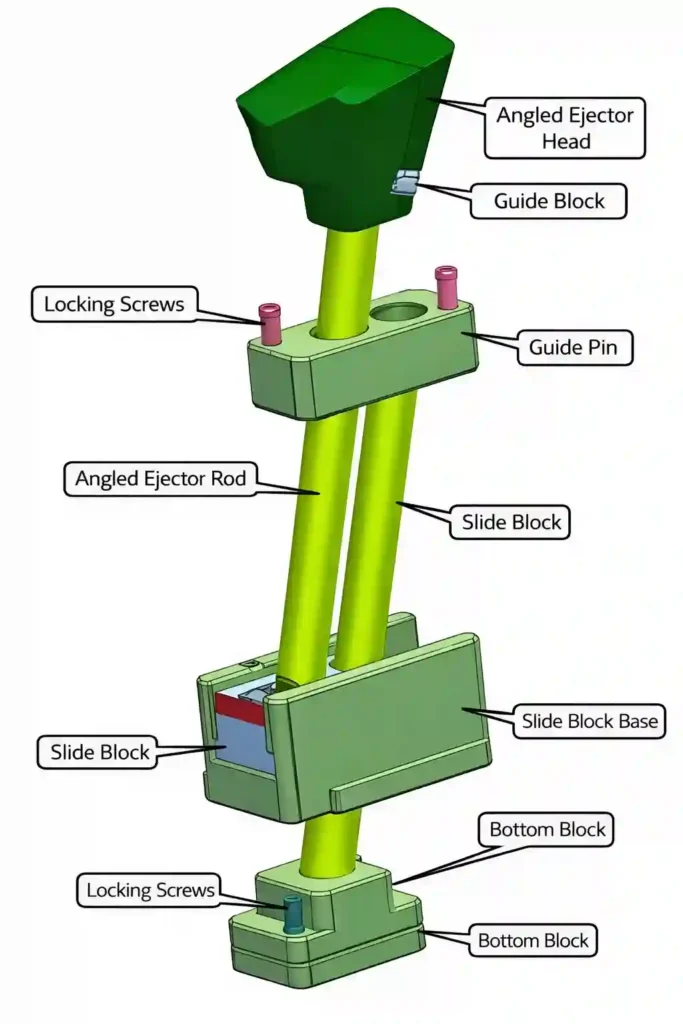
Lifter Angle
Lifter angles are typically 5° to 15°. Steeper angles increase stress on the lifter and may cause bending. The angle must be large enough to clear the undercut within the available mold opening stroke.
Lifter Head Design
The head of the lifter forms the undercut. It should have a slight taper (0.5–1°) to help the part release. Sharp corners at the base of the undercut should be radiused to avoid stress concentrations.
Lifter Body
The body should be as thick as possible to resist bending. Minimum thickness: 6–8 mm for small lifters, larger for bigger parts. Use through‑hardened tool steel (e.g., H13, S7) for durability.
Guiding
Lifters need precise guiding. Use bushings or guide pins to prevent twisting. The lifter should slide smoothly without binding.
Cooling
Lifters are difficult to cool. For high‑cycle molds, consider using beryllium copper or adding small cooling channels.
If you are unsure about the right slide or lifter design for your part, our engineers can help. We offer custom injection mold design services that include detailed slide and lifter layouts. We have designed thousands of complex molds and know what works.
Common Design Mistakes and How to Avoid Them
| Mistake | Consequence | Solution |
|---|---|---|
| Insufficient slide travel | Part hangs up, mold damage | Calculate required travel + safety margin |
| Lifter angle too steep | Lifter bends or breaks | Keep angle under 15°, use stronger steel |
| No wear plates on slide | Slide wears quickly, flash | Add hardened wear plates |
| Sharp corners on lifter head | Stress cracks, part breaks | Add radii at all corners |
| Poor cooling | Long cycle times, warpage | Add cooling channels or use conductive materials |
| Slide return spring weak | Slide not reset, crash | Use stronger springs or hydraulic return |
Real‑scenario risk: We once saw a mold with a lifter angle of 20°. After 10,000 cycles, the lifter bent and the mold had to be rebuilt. Reducing the angle to 12° and using a stronger steel fixed the problem permanently.
Design Checklist for Slides and Lifters
For Slides:
- Travel distance > undercut + 2 mm
- Angle pin angle ≤ 20°, less than slide travel angle
- Wear plates installed
- Cooling considered
- Positive return mechanism (springs or hydraulics)
For Lifters:
- Lifter angle 5–15°
- Lifter head has taper and radii
- Body thickness sufficient (≥6 mm)
- Guiding (bushings) provided
- Stress analysis performed for long lifters
Materials for Slides and Lifters
| Component | Recommended Material | Hardness |
|---|---|---|
| Slide body | H13, D2, or P20 (for low volume) | 48–52 HRC |
| Wear plates | Bronze or hardened tool steel | – |
| Angle pins | H13 or D2 | 50–54 HRC |
| Lifter body | H13, S7, or M2 | 50–54 HRC |
| Lifter head | Same as body | – |
For high‑abrasion materials (glass‑filled), consider coatings like TiN or DLC.
Designing for Manufacturability
When designing parts that need slides or lifters, keep these tips in mind:
- Minimize undercuts – Each undercut adds cost and complexity.
- Align undercuts with parting line – If possible, design so undercuts are on the same side.
- Avoid deep, narrow slots – They require thin lifters that may break.
- Provide adequate draft – Draft on the undercut itself helps release.
For a deeper understanding of how slides and lifters fit into overall mold design, read our detailed mold design guide.
Frequently Asked Questions
Q1: How much does a slide or lifter add to mold cost?
A: Each slide can add $2,000–$5,000 to the mold cost. Complex mechanisms add more. But they are necessary for many parts.
Q2: Can I avoid slides by redesigning the part?
A: Sometimes yes. Rotating the part or splitting it into two pieces may eliminate undercuts. Always consider design alternatives early.
Q3: What is the maximum angle for a lifter?
A: Typically 15°. Above that, stress increases and the lifter may bend. For deeper undercuts, consider a two‑stage lifter or a hydraulic core.
Q4: Do slides and lifters need maintenance?
A: Yes. Wear plates, pins, and springs should be inspected regularly. Proper lubrication extends life.
Q5: Can slides be used on both sides of the mold?
A: Yes, slides can be on the cavity side, core side, or both. They can also be angled in multiple directions.
Q6: What is the best steel for glass‑filled materials?
A: H13 or D2 hardened to 52–56 HRC. Coatings like TiN reduce wear further.
Summary
Slides and lifters are essential for molding complex parts with undercuts. When designed correctly, they run reliably for millions of cycles. When neglected, they cause downtime and expensive repairs. By following the guidelines in this article – proper angles, adequate travel, wear protection, and cooling – you can ensure your mold performs as intended.
At Miracles Manufacturing, we design and build complex molds every day. We understand the nuances of slide and lifter design and can help you get it right. Contact us to discuss your project.