
One of the most common questions from new designers is: why do plastic parts need a draft angle? The simple answer is that without it, parts stick in the mold and cannot be ejected. Injection molding draft angle refers to the taper added to vertical walls so the part releases cleanly from the mold. It might seem like a small detail, but getting it wrong can halt production and damage expensive tooling. In this guide, we explain what draft angles are, why they matter, how much draft you need, and how to apply them to your designs. Whether you are designing a simple housing or a complex component, understanding draft angle design will save you time and money.
What Is a Draft Angle?
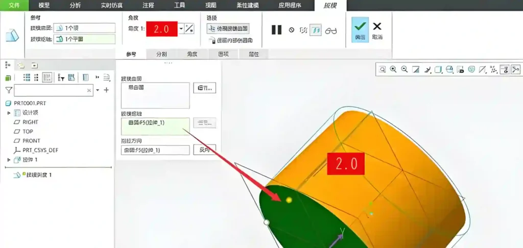
A draft angle is a slight taper applied to the walls of a plastic part that are perpendicular to the mold parting line. When the mold opens, the part shrinks onto the core. Without draft, friction holds the part in place and it may not eject. With draft, the part releases easily.
Draft is measured in degrees. A typical draft angle is 1° to 2° per side. It looks like a slight slope – barely noticeable but essential.
Why it works: As the part cools, it shrinks. Shrinkage pulls the part onto the core. Draft provides an air gap that breaks the vacuum and reduces friction.
If you are unsure about draft in your design, send us your 3D model. We will provide DFM feedback, including draft recommendations. Learn more about our custom injection mold design and manufacturing services.
Why Draft Angles Are Critical
Prevents Part Damage
Without draft, ejector pins can push through thin walls, leaving marks or breaking the part. Draft ensures the part slides off smoothly.
Protects the Mold
If a part sticks, operators may use excessive force or pry bars, damaging the mold surface. Scratches and dings lead to flash and poor cosmetics.
Reduces Cycle Time
Parts that eject easily allow faster cycles. No need to wait for stubborn parts or manual intervention.
Improves Surface Finish
Draft allows the part to separate cleanly without dragging across the mold surface, preventing scuff marks.
Real‑scenario risk: A client once designed a deep box with zero draft. The first mold trial ended with parts stuck so tightly that the mold had to be disassembled to remove them. Adding just 0.5° of draft solved the problem, but the mold modification cost thousands and delayed the project by weeks.
How Much Draft Do You Need?
The required draft depends on several factors:
- Material: Softer, stickier materials need more draft.
- Surface texture: Textured surfaces need extra draft (1.5° per 0.001 inch of texture depth).
- Depth of draw: Deeper parts need more draft.
- Part geometry: Ribs, bosses, and shut-offs may need additional draft.
General Guidelines by Material
| Material | Recommended Draft (per side) |
|---|---|
| ABS, Polystyrene | 0.5° – 1° |
| Polycarbonate (PC) | 1° – 2° |
| Nylon (unfilled) | 0.5° – 1.5° |
| Nylon (glass-filled) | 1° – 3° (due to abrasion) |
| Polypropylene | 0.5° – 1° |
| Acrylic (PMMA) | 1° – 2° |
| Flexible materials (TPE, TPU) | 3° – 5° |
Rule of Thumb
For most materials, 1° is safe, 2° is better. When in doubt, add more draft. It rarely hurts the part and always helps ejection.
Draft on Different Part Features
Exterior Walls
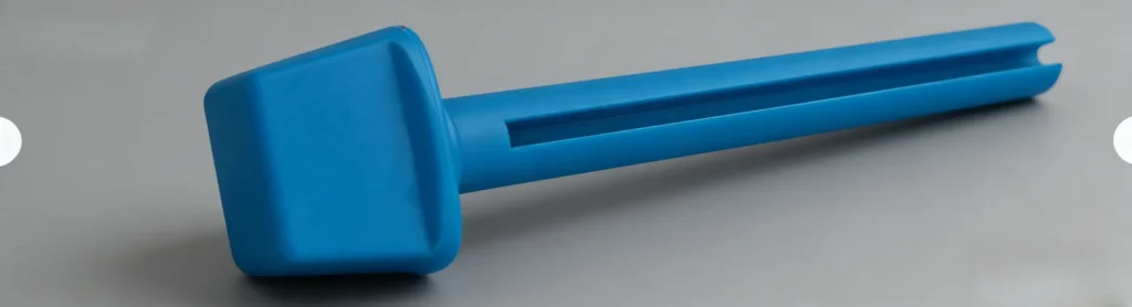
Apply draft to both the cavity and core sides. Typically 1° on each side works well. For tall parts, increase draft gradually.
Ribs and Bosses
Ribs should have 0.5° to 1° draft per side. Bosses need draft on the inside and outside. For blind bosses, consider using a collapsible core if draft is not possible.
Holes and Cutouts
Draft applies to the walls of holes as well. For through holes, draft can be on one side only.
Textured Surfaces
If the part has a texture (MT, VDI, SPI), the draft must be increased. A general rule: add 1° to 1.5° per 0.001 inch of texture depth. Always check with your mold maker.
How to Add Draft in CAD
Most CAD software has a “draft” tool. Steps:
- Select the faces to draft.
- Choose the neutral plane (usually the parting line).
- Specify the draft angle and direction (pull direction).
- Apply.
Tips:
- Draft in the direction of mold opening.
- Avoid zero‑draft areas – they will cause trouble.
- Check the model after drafting to ensure no unintended interference.
Common Draft Problems and Solutions
| Problem | Cause | Solution |
|---|---|---|
| Part sticks in cavity | Insufficient draft on cavity side | Increase draft, check for undercuts |
| Ejector pins push through | Draft too low, part stuck on core | Add draft, increase number of pins |
| Scuff marks on side walls | Part drags during ejection | Increase draft, improve surface finish |
| Warpage after ejection | Uneven cooling, sticking | Balance cooling, add draft |
| Flash at parting line | Mold damage from stuck parts | Repair mold, ensure draft is adequate |
Draft and Undercuts
Sometimes draft conflicts with undercuts. For example, a snap‑fit feature may need zero draft in one direction. In such cases, use side‑action cams or lifters to release the undercut. These features add cost, so try to design for straight‑pull ejection whenever possible.
Draft for Different Mold Types
- Two‑plate molds: Draft applies to all vertical surfaces.
- Three‑plate molds: Same rules, but gates may affect flow.
- Hot runner molds: Draft still needed.
- Family molds: All parts in the same mold must have draft in the same direction (if they share cores/cavities).
Custom Mold Design Services at Miracles Manufacturing
At Miracles Manufacturing, we review every part design for proper draft before cutting steel. Our engineers have decades of experience and can spot potential ejection issues early. We work with you to adjust draft angles, add texture correctly, and ensure your parts mold without headaches.
If you are unsure about draft in your design, send us your 3D model. We will provide DFM feedback, including draft recommendations.
Frequently Asked Questions
Q1: What is the minimum draft angle for injection molding?
A: For simple parts in easy‑flow materials like polypropylene, 0.5° can work. For most materials, 1° is recommended. Textured surfaces need more.
Q2: Can I have zero draft on some surfaces?
A: It is risky. Zero draft often leads to sticking. If absolutely necessary, consider adding lifters or increasing ejection force, but expect higher maintenance.
Q3: Does draft affect part strength?
A: Draft slightly changes wall thickness, but the effect on strength is usually negligible. In ribs, proper draft prevents stress concentrations.
Q4: How do I measure draft angle?
A: Use a protractor or CAD measurement tool. On a physical part, a draft angle gauge can help.
Q5: Is draft needed on both cavity and core?
A: Yes, typically. The part shrinks onto the core, so core draft is critical. Cavity draft helps the part release from the cavity side.
Q6: What if my part has no draft but is already in production?
A: You may need to modify the mold by adding draft through EDM or machining. It is expensive but possible. Better to catch it early.
Summary
Draft angles are a small feature with a big impact. They ensure reliable ejection, protect your mold, and keep production running smoothly. By following the guidelines in this guide, you can avoid common pitfalls and design parts that mold easily.
At Miracles Manufacturing, we help clients get draft right from the start or help with mold design guide. Contact us to discuss your next project.